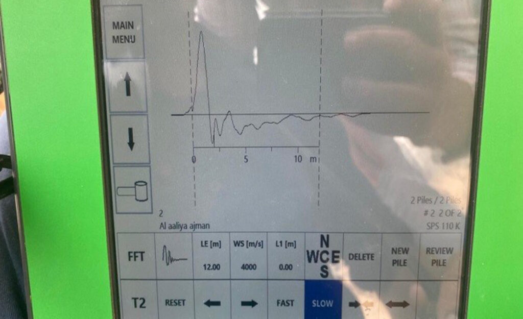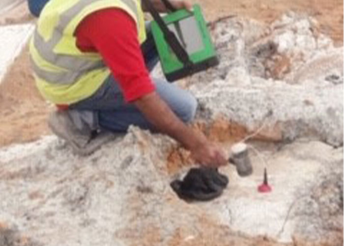

Low-strain integrity testing is designed to give information about the physical dimensions, continuity and consistency of materials used in piles. This test method covers the procedure for determining the integrity of individual vertical or inclined piles by measuring and analyzing the velocity response of a pile induced by an impact device applied axially to the pile normally at the pile head. The procedure to be adopted shall be in accordance with the guidance given in ASTM D 5882 standard procedure. It is important to clarify the following limitation of this technique:
01. For a successful low strain integrity testing, pile top surface must be properly prepared using a grinder or other tools as necessary to smooth uneven surfaces. Once low strain integrity data are collected, they should be analyzed thoughtfully using the reprocessing and signal enhancement facilities. For each and every data recorded the following points should be checked:
2. The observation of toe reflection depends on many parameters, such as the ratio of pile length to diameter and surrounding soil strata. If the toe is not apparent, the test is only partly successful, knowing that the most serious defects are in the upper portion of the shaft and deeper defects are often judged less serious if the shaft resistance above the defect is adequate to bear the load.


03. Regardless if the toe reflection is apparent or not, the main purpose of the low strain integrity testing shall remain to locate piles with serious defects, especially near the top. Furthermore, low strain integrity testing shall remain an important part in evaluating the suitability of the piles for their intended purpose, and should be conducted on all the production piles. It is important to mention here that a defect at depths of more than 10 – 15 meters is not likely to occur due to concrete overburden pressure below such depths, assuming that strict quality control practices were applied at the time of casting these piles.
04. The propagation speed c can be adjusted accurately if and only if the toe reflection is clear and the pile length is known with a high level of confidence, otherwise the wave speed may be assumed (generally 4000 m/s and may vary with +- 10 %). Based on this assumed wave speed, a pile toe reflection may be seen hence the pile length may be confirmed. It is to be noted that increasing the wave speed has the effect of predicting higher pile length, hence assuming accurately the wave speed is extremely important for checking the pile length.
5. A complicating factor in determining the wave speed in concrete c is the fact that the concrete is not homogeneous. The concrete quality will vary over the cross section and over the pile axis and this is caused by the pouring procedure and the difference in concrete pressure during the casting. This means that the stress wave velocity calculated will vary with the pile length. Hence, the stress wave velocity calculated with c = 2L/T (where L is the pile length and T is the time interval required for a shock wave to propagate twice through the concrete, i.e. from the time of the hammer blow and till getting the toe reflection) is a mean value for the whole pile and cannot be the same from one pile to another.
6. It is important to mention that it difficult to distinguish between reflections coming from soil conditions or from pile impedance changes, especially with soils that exhibit a relatively high friction where the integrity evaluation may be inconclusive. Furthermore, any decrease in impedance should be checked with respect to the nominal impedance where it is difficult to quantify the acceptable values, hence to quantify whether any decrease in impedance could be considered as minor or major problem.
Ready to take the next step? Contact us today and let’s make it happen!